
Feed-Check Valve
Description
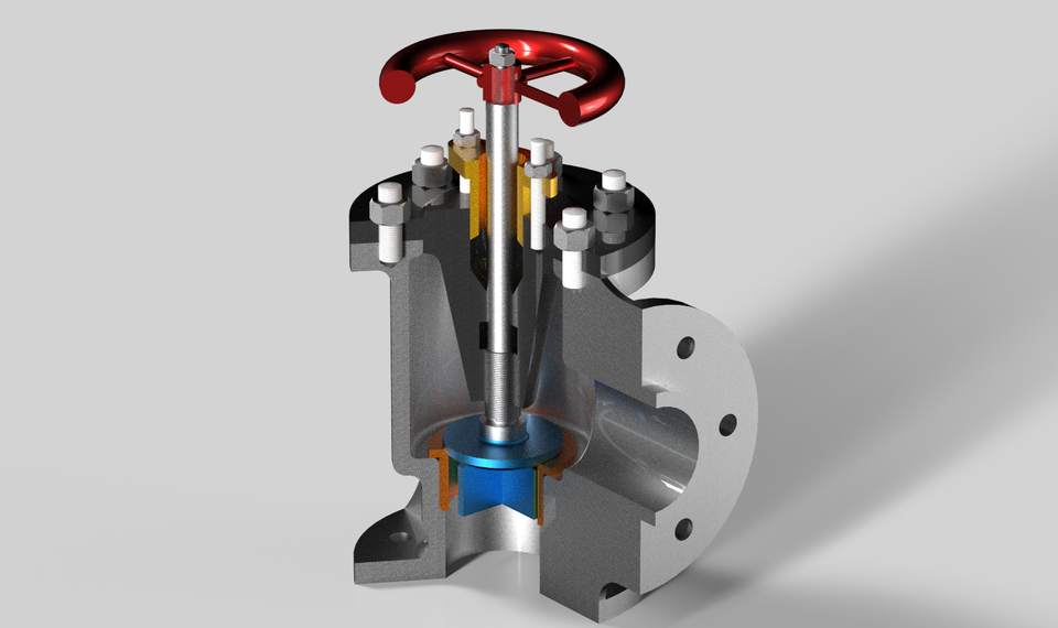
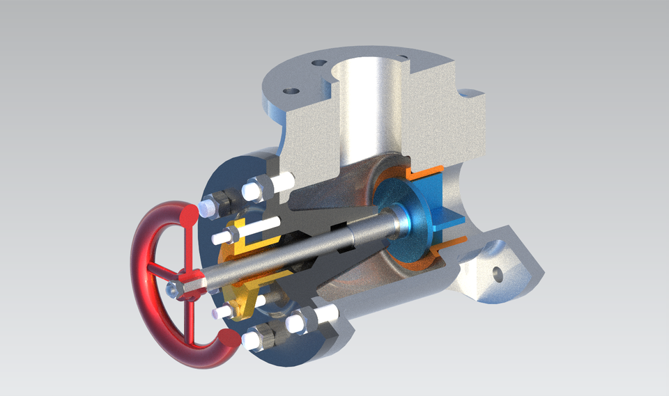
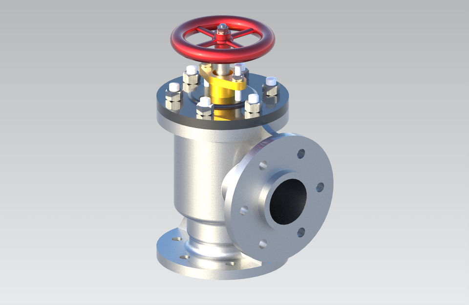
It is used in boilers to regulate the supply of feed water and to maintain the water level. It is fitted close to the boiler shell and in the feed pipe line. The valve prevents water from being returned to the supply line, due to steam pressure in the boiler. Hence, it functions like a non-return valve.
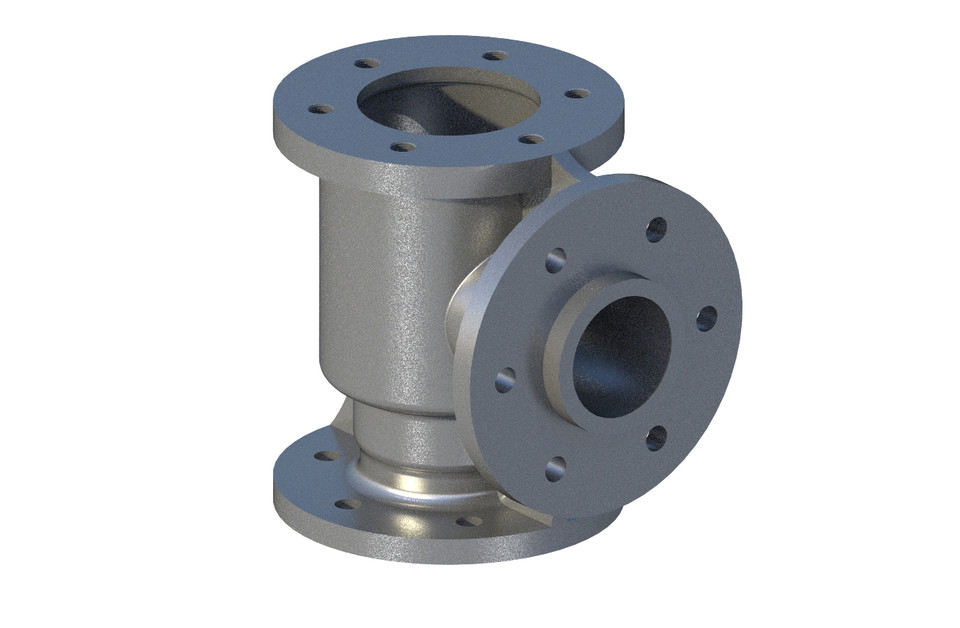
It consists of a body with two flanges at right angle and feed water enters at the bottom and enters the boiler through the side opening. The valve seat is introduced into the body of the valve from the top opening. The valve is located in the valve seat, which guides the movement of the valve. The spindle is screwed from bottom of the cover such that, the square end of the spindle projects out through the cover. Studs are screwed to the body and the spindle and cover assembly is fastened to the body by nuts. Studs are screwed to the cover and the gland is inserted into the cover and tightened by nuts. To prevent the leakage of water through the cover, packing material is introduced between the cover and gland. Hand wheel is located on the spindle such that, the square hole in the hand wheel meshes with the square portion of spindle. The hand wheel is fixed to the spindle by nut.
By operating the hand wheel, the spindle permits the valve to get lifted from the valve seat and allows feed water to enter the boiler.*
- The model has been created on Siemens NX.
- The constraints have been created by aligning CSYS to CSYS as interfaces.
- Also, the screw threads have been created by using WAVE Geometry Linker.
- All the components are in STL Format for 3D Printing Process.
*Narayana K.L., Machine Drawing 3rd Edition